Timer0 of pic16f is popular and very basic for creating short delays or… for creating small timing pulses. It is an 8bit timer with high priority interrupt. Which makes it perfect for creating time-critical applications like frequency counter, some industrial timing control system or any medical or industrial grade application.
To know more about the timer0 and its calculations you can always consult with datasheet of the microcontroller.
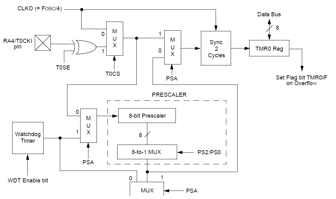
Clock Sources of Timer0
Like other timers, Timer0 also have two possible options for clock source,
1. Internal Clock Source.
In this mode, the internal clock frequency of the microcontroller is used as a clock source mean the attached crystal or any other clock source of the microcontroller is the clock source of timer0 as well.
2. External Clock Source.
When we want to provide some external source of the clock rather than the attached crystal of the microcontroller, this mode is called the external clocking mode. We use this type of clock to count the number of pulses. We can also count the timing of some external clock source. In this mode, the clock is provided to the pin RA4.
For creating delays, We mostly use Internal Clock Source. so if you are also going to use timer0 for delaying or Real Timer Clock purposes then you also need to use internal clock source. Which you may also change according to your timing desires and timing calculations. You may consult with this link as well for creating calculations of timer values.
Look the following diagram and you will be well aware of which registers to tackle with.

Connected Registers with Timer0 of PIC16f:
Following three registers are connected with timer0 of pic16f
1. TMR0, This is timer module register.
2. INTCON, This register is used for interrupt settings.
3. OPTION_REG: Clock source and pre-scaler settings are done in this register.
So, to correctly configure timer 0 we need to properly configure these three registers.
OPTION_REG
As mentioned earlier, This register is about pre-scaler and clock source for the timer0. Bit 7&6 are not used for timer0 but bit5-0 are for timer0 configurations.
Bit#5 T0CS
If we want to use this register for internal clock we need to set T0CS=0 and set this to 1 if external clock is used.
Bit#4 T0SE
This bit is used for selecting the transition of the clock.
Bit#5 PSA
Pre-scaler is shared between timer0 and watchdog timer. So if you want to use pre-scaler with timer0 then you must disable PSA bit in OPTION_REG
Bit#2-0 PS2-PS0 These bits are the value of pre-scaler in timer0 or for watchdog timer.
