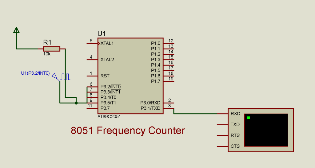
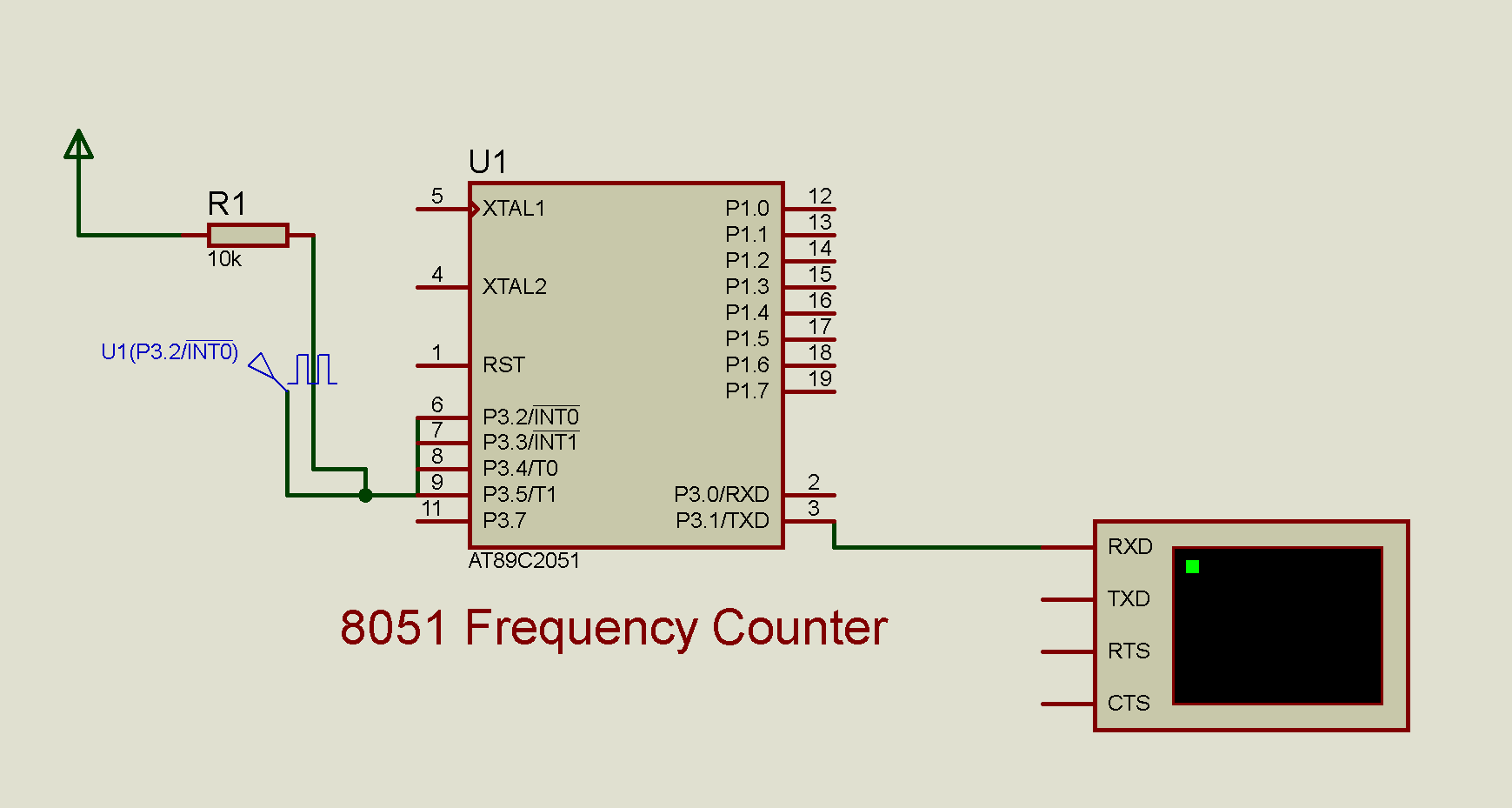
Today we are going to make a very simple 8051 Assembly code for a frequency counter example. We are going to make the example very simple and to the point just the way we normally do in our previous examples. Today’s focus is to demonstrate the very simple frequency counting algorithm implementation in 8051 assembly language. With this algorithm we are going to take a simple delay of 1 second using the 8051 timers. Meanwhile we initiate the external interrupt to count the pulses on External Interrupt pin of the 8051 microcontrollers. The External interrupt will count the number of pulses until the internal timer complete it’s one second delay. After the delay is complete the number of counts on external interrupt is our actual frequency.
For the sake of the simplicity, we are going to display the result on the serial terminal. We do not want to make the code goes extra big as the code is in Assembly language. We will output the frequency on the serial terminal. We are going to use the timer @2400 baud rate at the 12Mhz crystal. The simulation is done on the proteus 8 and the microcontroller used in the proteus is AT89c2051 to keep things simple.

What is a Frequency Counter?
A frequency counter is an electronic instrument that measures the frequency of an input signal. The frequency is defined as the number of occurrences of a repeating event per unit of time. In the context of this code, the frequency counter counts the number of pulses or cycles of a signal within a specified time frame (1 second in this case) to determine its frequency.
Frequency Counter Algorithm
The 8051 frequency counter algorithm initializes the microcontroller’s timers and serial communication, then enters a loop where it repeatedly clears the counter, enables interrupts, waits for a specified time (one second), disables interrupts, and transmits the counted pulses. The external interrupt service routine (ISR) increments the counter digits upon each pulse and handles the overflow by advancing to the next digit. The half-second delay subroutine creates precise timing using Timer 0, while the transmission subroutine converts the counter digits to ASCII and sends them serially. This process effectively measures the frequency of input pulses by counting them over a fixed time interval and sending the result for display or further processing.
Calculation of Limits
Given the above setup:
- Maximum Count: The maximum count before overflow is
9999. - Time Frame: The code counts pulses in a 1-second interval.
Therefore, the frequency measurement limit is:
- Maximum Measurable Frequency: 9999 pulses per second (or 9999 Hz).
- Minimum Measurable Frequency: 1 pulse per second (or 1 Hz).
In practical terms, the actual measurement limits may be slightly lower due to the overhead of executing instructions and handling interrupts. The effective frequency range for accurate measurement will be somewhat less than the theoretical maximum of 9999 Hz.
8051 Assembly code for frequency counter
Let’s dive into the actual code and try to understand the working of the code step by step. Here is the initial macro definitions of the code.
LEDS        EQU     P0

DIGIT1      EQU     30H
DIGIT2      EQU     31H
DIGIT3      EQU     32H
DIGIT4      EQU     33H

ORG         0
LJMP        MAIN

ORG         3H  ;EX0 VECTOR
LJMP        EX0_ISR
LEDS is defined as P0, the port we will use for LEDs. DIGIT1, DIGIT2, DIGIT3, and DIGIT4 are memory locations (30H, 31H, 32H, 33H) where we will store the digits of the counter.ORG 0 and LJMP MAIN set the starting point of our program.ORG 3H and LJMP EX0_ISR define the interrupt vector for external interrupt 0 (EX0).
MAIN:
    ;====== SERIAL INIT =============================
    MOV     TMOD,#22H    ;TIMER 1 , MODE 2
    MOV     TH1,#-13     ;2400 BAUD RATE @ 12MHZ
    MOV     TH0,#-200    ;PRELOAD VALUE
    SETB    TR0
    MOV     SCON,#52H    ;8-BIT , 1 STOP , REN ENABLED
    SETB    TR1    ;START TIMER 1
    SETB    IT0    ;EDGE TRIGGER
    MOV     IE,#10000001B    ;ENABLE EX0
    CLR     IE.7
    ;========== ======================================
Code language: PHP (php)TMODis set to22Hto configure Timer 1 in modeTH1is set to-13to get a baud rate of 2400 at a 12MHz clock.TH0is preloaded with-200for timing purposes.TR0andTR1are set to start Timer 0 and TimerSCONis set to52Hto configure serial communication.IT0is set to enable edge-triggered interrupts.IEis set to10000001Bto enable external interrupt 0 (EX0).
AGAIN:
    ACALL   CLEAR_COUNTER
    SETB    IE.7
    ACALL   HALF_SEC
    ACALL   HALF_SEC
    CLR     IE.7
    ACALL   TRANS_DATA
    SJMP    AGAIN
Code language: CSS (css)
The AGAIN loop clears the counter, enables interrupts, waits for half a second twice (total 1 second), disables interrupts, and transmits the counter data. CLEAR_COUNTER subroutine sets the counter digits to zero. HALF_SEC subroutine waits for half a second. TRANS_DATA subroutine transmits the counter digits serially.
EX0_ISR:
    INC     DIGIT1
    MOV     A,#10
    CJNE    A,DIGIT1,EX0_EXIT
    MOV     DIGIT1,#0

    INC     DIGIT2
    CJNE    A,DIGIT2,EX0_EXIT
    MOV     DIGIT2,#0

    INC     DIGIT3
    CJNE    A,DIGIT3,EX0_EXIT
    MOV     DIGIT3,#0

    INC     DIGIT4
    CJNE    A,DIGIT4,EX0_EXIT
    MOV     DIGIT4,#0

EX0_EXIT:
    RETI
Code language: CSS (css)
The EX0_ISR is the interrupt service routine for external interrupt 0. It increments DIGIT1 and checks if it reaches 10. If DIGIT1 reaches 10, it resets DIGIT1 to 0 and increments DIGIT2. The process repeats for DIGIT3 and DIGIT4.
HALF_SEC:
    MOV     R6,#25
L02:    MOV     R7,#100
L01:    JNB     TF0,$
    CLR     TF0
    DJNZ    R7,L01
    DJNZ    R6,L02
    RET
Code language: PHP (php)
The HALF_SEC subroutine uses Timer 0 to create a delay of half a second.
TRANS_DATA:
    MOV     A,DIGIT4
    ADD     A,#48
    ACALL   TX
    MOV     A,DIGIT3
    ADD     A,#48
    ACALL   TX
    MOV     A,DIGIT2
    ADD     A,#48
    ACALL   TX
    MOV     A,DIGIT1
    ADD     A,#48
    ACALL   TX
    MOV     A,#10
    ACALL   TX
    MOV     A,#13
    ACALL   TX
    RET
Code language: CSS (css)
The TRANS_DATA subroutine converts the counter digits to ASCII and transmits them serially.
TX:
    JNB     TI,$
    CLR     TI
    MOV     SBUF,A
    RET
The TX subroutine waits for the transmit interrupt flag (TI) to clear and then loads the accumulator (A) into the serial buffer (SBUF) for transmission.
Conclusion
This 8051 assembly code example demonstrates a simple frequency counter. It counts the number of pulses within a second and transmits the result serially. Understanding each part of the code helps in grasping the functionality of the 8051 microcontroller and assembly programming.
I hope you find this explanation helpful. Keep experimenting and learning. Happy coding!

One reply on “8051 Assembly Frequency Counter Example”
I would really like to expand on this code. But when I went to compile it I realised there is a chunk missing. The CLEAR_COUNTER sub-routine. Could you correct the code and repost so that I can go ahead with it?
Thank you