Today we are going to create a tiva c series tm4c123g blinky code in Keil uVision 5. The Tiva C Series TM4C123G LaunchPad is a microcontroller development board by Texas Instruments. These microcontrollers are based on the ARM Cortex-M4F processor architecture. It is a good option for beginners who want to learn about ARM-based microcontroller programming.
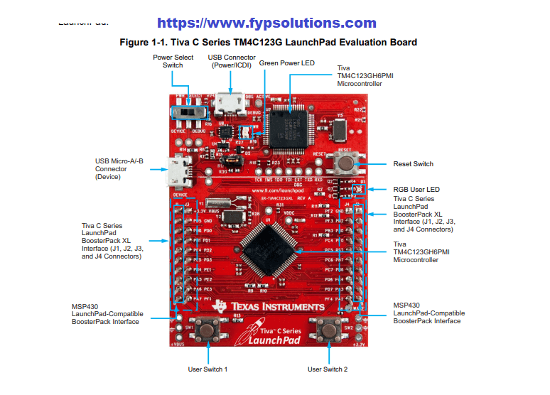
Table of Contents
Introduction
In this blog post, we will discuss how to perform a simple LED blinking application or “Blinky Application” using Keil software on the Tiva C Series TM4C123G Launchpad. We are going to explain how to blink on board LED on the Tiva C launchpad board which have onboard microcontroller of TM4C123G series. This microcontroller is ARM Context-M series microcontroller. Which means most of the ARM based logic is applicable with it. This is going to be very similar for our previous Create New Project in Keil uVision 5 for STM32 article.
Core Features of TM4C123G LaunchPad evaluation kit
Here are the list of main features enlisted on official page of from the TI EK-TM4C123GXL Evaluation board | TI.com.
- Low-Cost evaluation platform for Arm Cortex-M4F based microcontrollers (MCUs).
- 80-MHz Arm Cortex-M4F central processing unit
- 256kB of flash
- 32 kB of static RAM
- Integrated USB 2.0 support for USB host/device/on-the-go
- Two 12-bit analog-to-digital converter modules.
- UART, SPI, I2C, and CAN.
- PWM modules
Create New Project in Keil
Once download and Install the KEIL uVision for ARM-MDK from their official website. Once installed open the Keil and from the Project menu select create a new project option. This will lead you to select a project location to save. Name your project anything you want and then from the next window select the Device. From this selection pack make sure you already install the TIVA C Series Device Support package as well. If you have not installed it, you can install it from the Keil Device Pack installer option available in toolbar. Now if you already have your device support option available you can simply navigate to the search bar and type your microcontroller name which is TM4C123GH6PM.

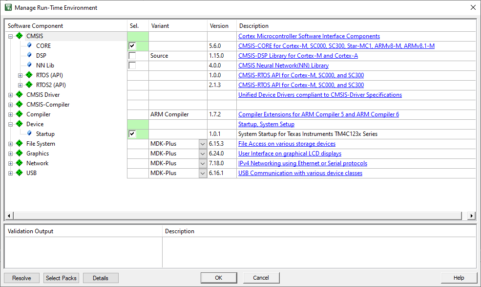
Once selected, Press OK. It will take you to the next window which is about managing the Run-Time Environment. Where you have to select the CORE option under the CIMSIS and from the Device Option select the Startup. This will look something like below.
Once done, press OK button. Now your project for Tiva C TM123x series is ready. You can add a new main.c by Pressing Right-Click button on your source group and selecting the option to add new file. There select the C file option and name your file as main.c.

After clicking Add Your file is added into the source group and you are ready to write your LED blinking code.
Understanding GPIOs
We are now have to understand the GPIO related registers. This will help us to better understand the register level programming for the TM4C123G microcontrollers. This information is fetched from the Official Datasheet of the microcontroller. Here is the basic information found from the Datasheet related to GPIO section.
- The GPIO module is composed of six physical GPIO blocks, each corresponding to an individual GPIO port (Port A, Port B, Port C, Port D, Port E, Port F)
- Pin muxing allows use as GPIO or one of several peripheral functions
- 5-V-tolerant in input configuration
- Ports A-G accessed through the Advanced Peripheral Bus (APB)
- Weak pull-up or pull-down resistors
- 2-mA, 4-mA, and 8-mA pad drive for digital communication; up to four pads can sink 18-mA
- for high-current applications
- Each GPIO port can be accessed through one of two bus apertures
- The Advanced Peripheral Bus (APB) is backwards-compatible with previous devices.
- the Advanced High-Performance Bus (AHB), offers the same register map but provides better back-to-back access performance than the APB bus.
GPIO Related Registers
If we look into the header file, we will get the GPIO type definition with following list of registers.
/**
  * @brief Register map for GPIOA peripheral (GPIOA)
  */

typedef struct {                                    /*!< GPIOA Structure                                                       */
  __I  uint32_t  RESERVED[255];
  __IO uint32_t  DATA;                              /*!< GPIO Data                                                             */
  __IO uint32_t  DIR;                               /*!< GPIO Direction                                                        */
  __IO uint32_t  IS;                                /*!< GPIO Interrupt Sense                                                  */
  __IO uint32_t  IBE;                               /*!< GPIO Interrupt Both Edges                                             */
  __IO uint32_t  IEV;                               /*!< GPIO Interrupt Event                                                  */
  __IO uint32_t  IM;                                /*!< GPIO Interrupt Mask                                                   */
  __IO uint32_t  RIS;                               /*!< GPIO Raw Interrupt Status                                             */
  __IO uint32_t  MIS;                               /*!< GPIO Masked Interrupt Status                                          */
  __O  uint32_t  ICR;                               /*!< GPIO Interrupt Clear                                                  */
  __IO uint32_t  AFSEL;                             /*!< GPIO Alternate Function Select                                        */
  __I  uint32_t  RESERVED1[55];
  __IO uint32_t  DR2R;                              /*!< GPIO 2-mA Drive Select                                                */
  __IO uint32_t  DR4R;                              /*!< GPIO 4-mA Drive Select                                                */
  __IO uint32_t  DR8R;                              /*!< GPIO 8-mA Drive Select                                                */
  __IO uint32_t  ODR;                               /*!< GPIO Open Drain Select                                                */
  __IO uint32_t  PUR;                               /*!< GPIO Pull-Up Select                                                   */
  __IO uint32_t  PDR;                               /*!< GPIO Pull-Down Select                                                 */
  __IO uint32_t  SLR;                               /*!< GPIO Slew Rate Control Select                                         */
  __IO uint32_t  DEN;                               /*!< GPIO Digital Enable                                                   */
  __IO uint32_t  LOCK;                              /*!< GPIO Lock                                                             */
  __IO uint32_t  CR;                                /*!< GPIO Commit                                                           */
  __IO uint32_t  AMSEL;                             /*!< GPIO Analog Mode Select                                               */
  __IO uint32_t  PCTL;                              /*!< GPIO Port Control                                                     */
  __IO uint32_t  ADCCTL;                            /*!< GPIO ADC Control                                                      */
  __IO uint32_t  DMACTL;                            /*!< GPIO DMA Control                                                      */
} GPIOA_Type;


Code language: PHP (php)
We will be interested in DATA and DIR registers which will be used for configuring the GPIO pins as Output and then writing DATA to the respective GPIO pin.
Tiva C LaunchPad Onboard LEDs
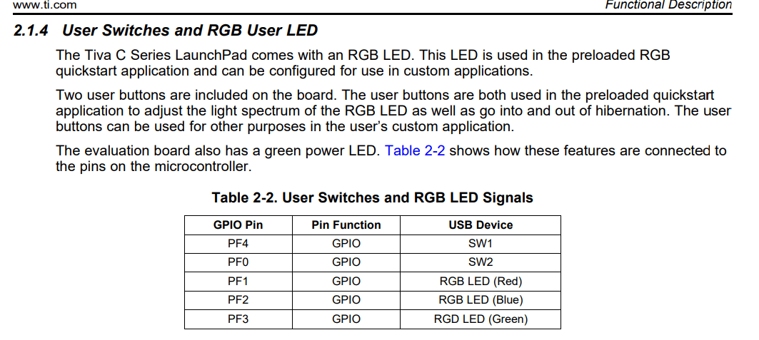
Before writing the LED blinking code we need to look for on board LEDs available in the Tiva C TM4C123G launch pad. If we look into the Tiva™ C Series TM4C123G LaunchPad Evaluation Board User’s Guide It will tell us that there are Three on board LEDs are available which are RGB LEDs. We can use them to test our LED Blinking code. There LEDs are attached with the PORTF of the TM4C123G microcontroller. The RED Led is attached with the PORTF.PF1 pin, Green LED is attached with the PORTF.PF2 pin and the Blue LED is attached with the PF3 of the PORT F of the microcontroller.
TM4C123G LED Blinking Code
Now we are writing the actual LED blinking code on the bare metal CMSIS Core. We have to include the header file first which will contain all the registers definitions. Here is how we can include the main header file on the top of our main.c file.
#include "TM4C123.h" // Device headerCode language: PHP (php)This will automatically call the respective include "TM4C123GH6PM.h" which is our on board microcontroller in the Tiva C TM4C123G launch pad.
Enable Clock for GPIOF
Because our LEDs are attached with the GPIOF, before using that GPIO we have to enable the clock for the respective GPIO. We can do that with the SYSCTL->RCGCGPIO Register like this.
SYSCTL->RCGCGPIO |= (1U << 5);  // enable clock for GPIOF
Code language: C++ (cpp)
Set GPIO Directions as Output
Before writing to the GPIO Data register we have to make it output. This will make sure that the respective bit is available for writing output. We can accomplish this task by simply making the GPIO F->DIR register and GPIOF->DEN.
GPIOF->DIR |= (LED_RED | LED_BLUE | LED_GREEN); // set pins 1, 2 and 3 as outputs
GPIOF->DEN |= (LED_RED | LED_BLUE | LED_GREEN); // enable digital function on pins 1, 2 and 3
Code language: PHP (php)
Creating a Delay function for Tiva C Launch pad board
Next thing is to create a Delay function. We are going to create a simply loop based delay function for wasting the time. This delay is not accurate but do the purpose of letting us blink the RGB LEDs of Tiva C TM4C123G launch pad evaluation board.
void Delay(void)
{
 unsigned long volatile time;
 time = 145448;
 while(time){
     time--;
 }
}
Code language: C++ (cpp)
There is another 0.1ms delay routine which is also for loop based from the GitHub link.
// Creates 0.1ms delay
void Delay2(void){
 unsigned long volatile time;
 time = 727240*200/91000;  // 0.1 ms
  while(time){
 time--;
  }
}


Code language: C++ (cpp)
Complete LED blinking Code
Here is the final complete LED blinking code which blink three on board RGB LEDs of Tiva C launch pad board together. Because we are toggling all three LEDs together, it will mimic the White color light. Here is the complete code which we will upload to our board.
#include "TM4C123.h"                    // Device header

#define LED_RED   (1U << 1)
#define LED_BLUE  (1U << 2)
#define LED_GREEN (1U << 3)


void Delay(void)
{
 unsigned long volatile time;
 time = 145448;
 while(time){
   time--;
 }
}

// Creates 0.1ms delay
void Delay2(void){
 unsigned long volatile time;
 time = 727240*200/91000;  // 0.1 ms
  while(time){
 time--;
  }
}

int main(void)
{
unsigned long volatile delay;
 SYSCTL->RCGCGPIO |= (1U << 5);  // enable clock for GPIOF
  GPIOF->DIR |= (LED_RED | LED_BLUE | LED_GREEN); // set pins 1, 2 and 3 as outputs
  GPIOF->DEN |= (LED_RED | LED_BLUE | LED_GREEN); // enable digital function on pins 1, 2 and 3


while(1){
 int i=0;
 GPIOF->DATA |= (LED_RED | LED_BLUE | LED_GREEN);
 for(i=0;i<10;i++)
 Delay();
 GPIOF->DATA &= ~(LED_RED | LED_BLUE | LED_GREEN);
 for(i=0;i<10;i++)
 Delay();
}
}
Code language: C++ (cpp)
Uploading code to the Tiva C board
To upload the code in the Tiva C launch pad from the Keil uVision 5 we have to do the debugger setting from the project settings. On the project window, select the Target and right click, from the menu select the options or press the Alt-F7. This will open the Options for Target 1 window. Goto the Debug tab and select the Stellaris ICDI options.
You can download STELLARIS_ICDI_DRIVERS Driver or library | TI.com. There are no support available now in Keil uVision 5 for the Stellaris ICDI. Which is also reported in this forum where a user says
I do not see the Stellaris ICDI option from the dropdown to select the ICDI. I am using uVision 5
No Stellaris ICDI in Debugs Tab – Keil forum – Support forums – Arm Community
Thank fully some folks says "we have created an add-on installer that you can use to get back Stellaris ICDI support in MDK:” So you simply navigate to this UVISION: Stellaris ICDI Debug Adapter Support (arm.com) and download and install the available attachments.
Final Output
Here is the final output after uploading the code into the board.

Resources and Datasheets
Here I am presenting the official documentations about the board from Texas Instruments (TI) about this Tiva C series TM4C123G Launchpad which comes handy while developing codes for bare metal programming on CIMSIS core for the board.
