Want to create a digital counter using a 7-segment display and an 8051 microcontroller? This comprehensive guide walks you through the process step-by-step, from wiring connections to code examples in both assembly and C. We will demonstrate the 7 segment interfacing code in assembly as well as 7 segment interfacing C code with keil uvision compiler. Seven segment is one of the most common type of display which is used almost 70% of the embedded systems. It is not costly and can be used in budget saving embedded system product.
Table of Contents
What is 7 segment display
Seven Segment display is basically collection of 7 LEDs forms in Numeric number 8. Because they are just LEDs thus, they could be formed in either common Anode or Common Cathode. Which is why we should be very clear either we are driving common anode 7 segment display or common anode seven segment display. With the 8051 and most of other negative edge triggered digital circuits Common Anode displays are popular. Which means, we have to provide the negative signal on the segments and have to provide a positive on the common pin. If you are not comfortable with accessing the IOs of the 8051 microcontroller please check a simple LED blinking code with 8051 and the 8 led blinking code in assembly language article in our webiste. Applying a high logic on the Anode pin is commonly done with the help of some PNP transistor which we will look when we do the multiple seven segment display interfacing with microcontroller.
Components List
Let’s summarize what kind of components we will be using in this experiment.
- AT89C51 Microcontroller: The main processing unit that controls the display
- Single-Digit Seven-Segment Display(Common Anode): A Common Anode display device with 7 segments (a-g) and an optional decimal point (h) to represent digits.
- Current-Limiting Resistors (8 x 330 ohms or 470 ohms): These resistors protect the LED segments in the display by limiting the current flowing through them
- Breadboard or Printed Circuit Board: A platform for connecting components and prototyping circuits
- Jumper Wires: Used to connect components on the breadboard or PCB
- 5V DC Power Supply: Provides power to the microcontroller and display
- 10k ohm Resistor pack: For pull-up resistors or and with the microcontroller reset circuit
- 33pF Ceramic Capacitors (2): For crystal oscillator connections
- 10μF Electrolytic Capacitor: For power supply filtering.
- 12Mhz Crystal: For providing external clock to the microcontroller
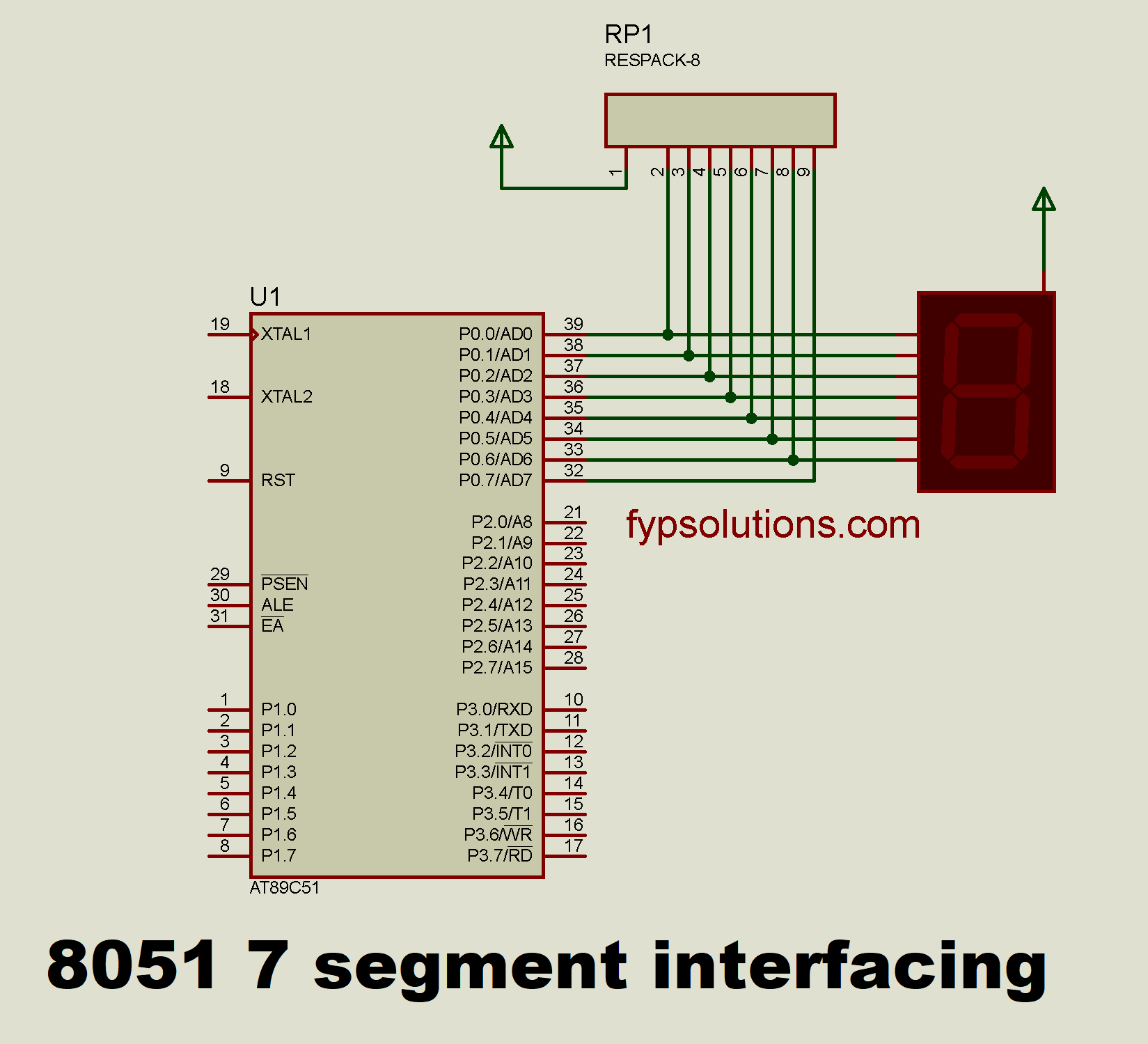
Wiring Connections
- Connect the common pin of the seven-segment display to the +5V because we are using the common anode 7 segment display.
- Connect the segments (a-g) to individual I/O pins of the microcontroller through current-limiting resistors. We are going to use P0 for this purpose. The specific pins would be from P0.0 to P0.7 which is pins from 39 of the AT89C51 microcontroller upto pin number 32. You have to connect the
asegment of the seven segment with the P0.0 (39) andbsegment with P0.1(38)… and finally theGsegment with the P0.6(31) of the AT89S51/AT89C51 microcontroller. - Connect the power supply to the microcontroller and display, ensuring correct voltage and polarity.
- Add 10K pullup resistors to the P0. You can use a resistor pack as shown in the circuit below.
- Add 12Mhz crystal to the external osccilator pins of the microcontroller which are 18 and 19 pin of the AT89C51/AT89S51/AT89S52 microcontroller. You can check the datasheet of your 8051 varient microcontroller and look for the correct pins to choose.
- Add 33pf ceramic capacitors with the external crystal and the ground
- Add the Reset circuit on Pin 9 of the microcontroller.
Simple Code for Up Counter 8051 7 segment assembly code
Let’s look for the assembly code with the simplest possible approach to use 7 segment display to display the numbers from 0 to 9 one by one in up counter manner. We are first of all going to have a look for the 7 segment codes which when put on the P0 will result in a specific number displayed on the 7 segment display. So we have to make the code for each of the number from 0 to 9. Even if we want to display the other characters like, C,d,E,F etc we have to calculate the appropriate binary number for the encodings.
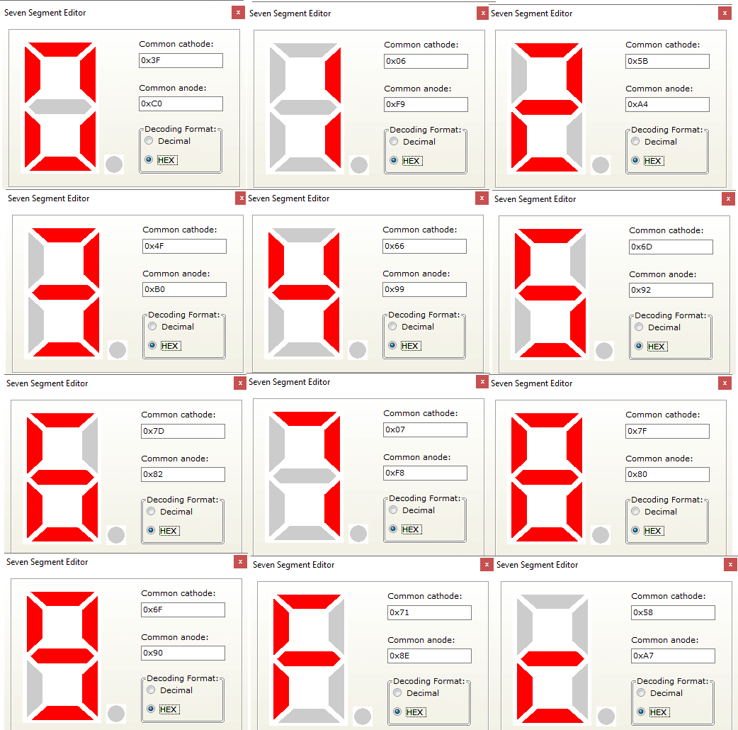
In our case the codes will be like this.
;================================================
;
;        SEG01.ASM
;
;================================================

SEG_DISP EQU P0

;================================================

START: MOV SEG_DISP,#01000000B ;0
 ACALL DELAY3

 MOV SEG_DISP,#01111001B ;1
 ACALL DELAY3

 MOV SEG_DISP,#00100100B ;2
 ACALL DELAY3

 MOV SEG_DISP,#00110000B ;3
 ACALL DELAY3

 MOV SEG_DISP,#00011001B ;4
 ACALL DELAY3

 MOV SEG_DISP,#00010010B ;5
 ACALL DELAY3

 MOV SEG_DISP,#00000010B ;6
 ACALL DELAY3

 MOV SEG_DISP,#01111000B ;7
 ACALL DELAY3

 MOV SEG_DISP,#00000000B ;8
 ACALL DELAY3

 MOV SEG_DISP,#00010000B ;9
 ACALL DELAY3

 SJMP START

;======== DELAY3 ================================

DELAY3: MOV R5,#5
D3L3: MOV R6,#255
D3L2: MOV R7,#255
D3L1: DJNZ R7,D3L1
 DJNZ R6,D3L2
 DJNZ R5,D3L3
 RET

Code language: ARM Assembly (armasm)
This is a simplest approach where we put the segment codes on the respective port which is P0 in our case. We put the hard coded binary numbers which will represent a digit from 0 to 9 and the correct number would be displayed. This is the proteus simulation result for the code.

Improving the Assembly Code with Data Tables
By storing segment patterns in a data table, we can achieve several benefits. For example, instead of repeating code for each digit, we store patterns once and reduce memory usage. Also the Code readability is improved and the code becomes more organized and easier to understand. Because segment patterns are clearly defined in the table. This Modifications to segment patterns can be made in a single location (the table) which simplify code maintenance.
Because our 7 segment codes are constant and never going to change, we can shift these constant values to the code memory of the microcontroller. We can achieve this by defining the data table in the code memory with the db instruction. Which means to define a byte in the code memory. Later we can retrieve this with the DPTR register by pointing to the address of the code memory which could be accessed through the label provided to the data table while defining the data table.
ORG 1000H ; Example lookup table
TABLE: DB 4, 8, 15, 16, 23, 42

MOV DPTR, #TABLE ; Load base address of table
MOV A, #3         ; Index for desired value
MOVC A, @A+DPTR   ; Fetch value at address (A + DPTR)
; Now A contains the value 15 from the table
Code language: ARM Assembly (armasm)
As you can see in the above code sample we defined the TABLE with the DB directive and later fetch the desired value by indexing it using A register and the DPTR register with the help of movc a,@a+dptr instruction. Now we can refactor our above counter code to adopt these changes and create a better assembly code for the 8051-microcontroller assembly language for 1 digit up counter by interfacing 7 segment display.
;================================================
;
;   SEG02.ASM - Enhanced segment display code
;
;================================================

SEG_DISP EQU P0  ; Define segment display port

ORG 0000H        ; Set starting address

;================================================

MAIN:
    MOV R0, #0    ; Initialize digit counter

DISPLAY_LOOP:
    MOV DPTR, #SEG_TABLE ; Load segment patterns
    MOV A, R0            ; Get current digit
    MOVC A, @A+DPTR      ; Fetch pattern from table
    MOV SEG_DISP, A      ; Display pattern

    ACALL DELAY3           ; Call delay subroutine

    INC R0                ; Increment digit counter
    CJNE R0, #10, DISPLAY_LOOP ; Loop for all digits

    SJMP MAIN             ; Repeat indefinitely


;======== DELAY3 ================================

DELAY3: MOV R5,#5
D3L3: MOV R6,#255
D3L2: MOV R7,#255
D3L1: DJNZ R7,D3L1
 DJNZ R6,D3L2
 DJNZ R5,D3L3
 RET

;================================================

SEG_TABLE:
    DB 01000000B  ; Pattern for digit 0
    DB 01111001B  ; Pattern for digit 1
    DB 00100100B  ; Pattern for digit 2
    DB 00110000B  ; Pattern for digit 3
    DB 00011001B  ; Pattern for digit 4
    DB 00010010B  ; Pattern for digit 5
    DB 00000010B  ; Pattern for digit 6
    DB 01111000B  ; Pattern for digit 7
    DB 00000000B  ; Pattern for digit 8
    DB 00010000B  ; Pattern for digit 9
END
Code language: ARM Assembly (armasm)
Here is the quick summary of applied improvements in the code.
- Data Table for Segment Patterns: Stores patterns in a table for better organization and readability.
- Pointer Access for Patterns: Uses
DPTRandMOVC A, @A+DPTRto efficiently retrieve patterns from the table. - Digit Counter: Iterates through digits using a counter for a structured loop.
8051 7 segment C code
Now let’s translate the above code into the Keil uVision C code. Although we used the Keil uVision but this code is basicllay pure C base code and could be used with other compilers as well as with other microcontroller by simply chaning the respective port accessing which could be done by checking respective microcontroller’s datasheet. Here is the complete C version of the above code.
#include<reg51.h>

#define SEG_PORT P0
    unsigned char seg_code[] = { 0x40, 0x79, 0x24,0x30,0x19,0x12,0x02,0x78,0x00,0x10};

void delay(unsigned int time) /*ruf estimated delay */
{

    //defining loop based delay
    unsigned int i,j;
    for(i=0;i<time;i++){
       for(j=0;j<1275;j++);
     }
}
void main()
{

    unsigned int i;
    while(1)
    {
        for(i=0;i<10;i++)
{
            SEG_PORT=seg_code[i];
            delay(100);
        }
    }
}

Code language: C++ (cpp)
Common Troubleshooting Tips
One you wire up everything in real hardware, you may find some issues which you need to address. There could be software or hardware related issues. Let’s discuss some basic troubleshooting tips which will help you to figure out if something goes unexpected or wrong or don’t work at all.
Dim or flickering display
If you display is too dim or flickers a lot you should focus on two things. For the flickering make sure that your connections are not loose. Sometimes the loose connections will flicker the display. For the dim light make sure that you used the appropriate 5 volt on the common anode pin and the use of current limiting resistors are correct. Sometimes decreasing the resistor value will make a bright display.
Incorrect digit display
If everything works fine but the digit being displayed are wrong and do not properly shows the number you expected. This could be due to two reasons, one and foremost reason which you should check is either you provided the correct binary or hexadecimal value into your code and it is according to the segment wiring connections you made. Double check that binary patterns and match it with the corresponding wrongly displayed number. Second thing could be the missing connection between the IO pin and the respective digit. If you constantly see that one segment is off and do not goes on in any displayed digit specifically when digit 8 comes all segments should light up, if that is not the case there is some missing wiring connections between that segment and the respective microcontroller pin.
No display
If you do not see anything being displayed make sure your microcontroller is functional. You may try blinking the LED first and make sure that LED is blinking properly which will ensure that the microcontroller clock is working and the power supply is working and the reset circuit is correct. If even the LED is not blinking first of all check the 5v power supply on the Vdd and Ground pins of the microcontroller. After that make sure you check the crystal oscillation is working and the Reset circuit is properly functioning.
